1. Preparing for Calibration
- First connect the lens and set the software to playback mode. Switch to the 2D view, then cover or remove all reflective marker points within the capture volume.
- You can click Show All Cameras at the top of the 2D view to monitor all cameras simultaneously, or double-click individual cameras in the 2D view to view only the selected one. The number in parentheses at the bottom-left corner of each camera indicates the number of reflective marker points visible to that camera.
- Remove extraneous points from the site, which often occur due to:
- Bright sunlight;
- Reflective surfaces on metal tables, chairs, shelves, and flooring
- Reflective stickers/logos, jewelry on clothing, shoes, and hats
- Stray reflective markers scattered in the captured scene.
- Common methods for removing clutter:
- Close the curtains to block out sunlight
- Remove reflective objects from the scene
- Adjust the camera's aperture
- Adjust the device's threshold parameters in the software's 2D view (usually between 200 and 600)
- Adjust the camera's brightness in the software's 2D view
- Use software for mask processing.
- The maximum and minimum values can be set in the "Minimum Point Diameter/Maximum Point Diameter" section below the device panel to filter the diameter range of the "marker" in the 2D view.
- Mask Processing
- Manual Mode: Double-click the cameras to be processed in the 2D view to zoom in on a single screen. Press and hold the mouse wheel in the 2D view to drag and drop, frame the area with impurities, and the impurities will be removed. You can repeatedly select boxes until all the miscellaneous points in the view are removed.
- Automatic Mode: Click the automatic masking button in the toolbar above the 2D view, and all 2D points in the view will be masked. Click "Clear Mask" to delete all masks. Using "Clear Mask" in a single view will only clear the mask in the current view (as shown in the figure). When selecting an automatic mask, it is necessary to clear useful and real reflective markers within the venue.
- To delete a specific area in the mask box caused by incorrect operation, click the left mouse button to select the area, and then click the right mouse button.
.png)
8.1.1
- After the above operations are completed, the calibration personnel should hold the T-shaped calibration rod and swing it in the field. Another person can observe whether there is a number greater than 3 in the bracket at the bottom left corner of the 2D view. If so, it indicates that there are impurities in the camera's field of view. Steps 5 and 7 can be repeated for processing until the cameras reach the optimal calibration state.
warning
The latest version supports calibration even when there are a small number of noise points in the scene. However, to ensure calibration accuracy, it is still recommended to keep noise points to a minimum.
Use the Mask area to simulate the underwater camera perspective
- After installing the underwater camera, it becomes difficult to adjust the camera once water is filled in the area. Therefore, a simple field of view simulation should be conducted before filling the water to reduce subsequent adjustment work. You can set a Mask area in the 2D view to obscure the upper, lower, left, and right observation angles of the camera, simulating the situation where the field of view decreases after the camera enters the water.
- You can open the Mask area settings by clicking the gear button ‘Obscure Settings’ in the toolbar at the top left corner of the 2D view.
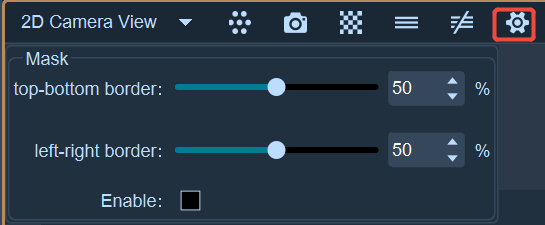
- You can set the Mask area for the upper and lower or left and right boundaries of the 2D view by entering values in the input box, dragging the progress bar, or clicking the up and down arrows.
- Check the enable checkbox to activate the set Mask area. The upper and lower or left and right boundaries of the 2D view will display a blue Mask area, distinguishing it from the manually drawn black Mask area.
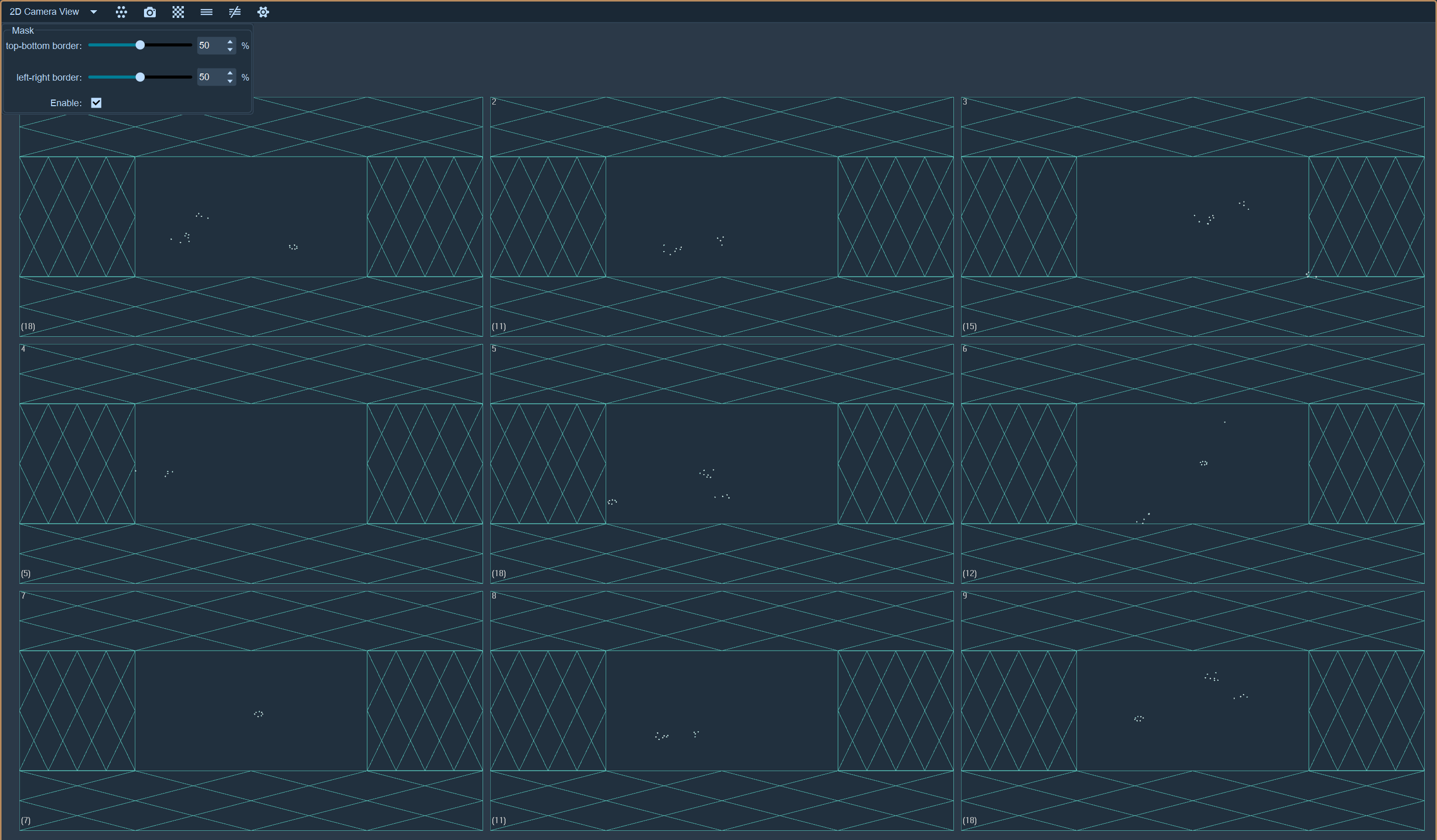
- You can also enter single view to set the Mask area for a single camera.